
Engineering Assessment of an Existing Separator
Filtration and Separation Basics by JCI
Engineering Assessment of an Existing Separator
A separator is engineered for the operating conditions defined at the time of design. Over the life of a facility, those conditions change. JCI is regularly asked to review an existing separator, typically for one of a few reasons: liquid carryover in the gas, a need for additional throughput, poor liquid-liquid separation, or contamination the existing internals were never designed to handle.
Process conditions rarely hold constant. Reservoir pressure declines over the life of a field, and the operating pressure and flow rates at the separator shift accordingly. A facility's throughput target may rise, or the governing constraint may sit in another piece of equipment entirely. Fluid composition changes as new wells or formations are brought online. Each factor changes the duty the separator is asked to perform. Declining operating pressure is a common driver: as pressure falls, gas density falls with it, and the inlet momentum under the conditions now in effect can differ substantially from the design case. JCI takes inlet momentum into consideration based on the current and planned operating conditions — but momentum at the inlet only means something in the context of the rest of the vessel. Published momentum guidelines empirically describe an acceptable degree of liquid shatter at the inlet device; they are one input to a holistic assessment of the separator, not a standalone pass or fail.
Carryover through the mist eliminator is one of the most common reasons for a review, and it occurs as a result of a few distinct mechanisms:
Gas velocity exceeds the allowable velocity through the mist eliminator.
The shape, location, or orientation of the mist eliminator produces maldistribution — localized regions of high velocity that drive carryover even when the average velocity looks acceptable.
The media is not dense enough for the service, such as a low-density mesh or a vane-only device in a high-pressure application.
Contamination has partially or fully plugged the device, again raising local velocity.
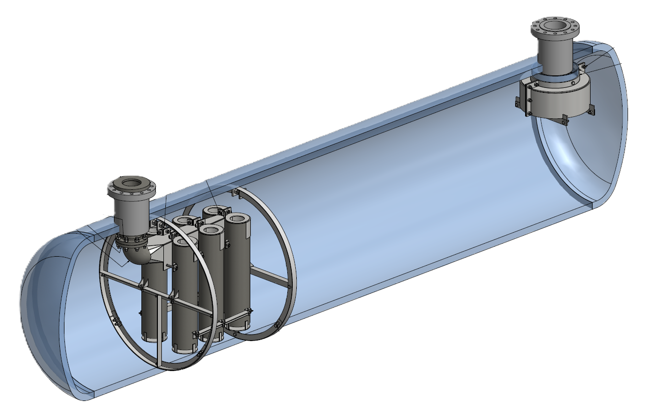
Figure 1 – An example of internals included in a retrofit kit for a horizontal separator.
Identifying which mechanism is at work is what determines the correction. That requires looking at the separator as a whole, because a limitation in one aspect of the design frequently presents as a problem in another. An inadequate inlet device or insufficient gas disengagement space, for example, can deliver excessive liquid to the mist eliminator — a condition corrected by addressing the inlet device or the location of the mist eliminator, not by changing the mist eliminator itself.
JCI analyzes the various aspects of the existing design and how they work together: the inlet nozzle size, geometry, and inlet device; the gas disengagement space; the liquid section and the retention time available for liquid-liquid separation; and the outlet mist eliminator's size, type, and configuration. Contamination such as waxy hydrocarbons, paraffins, asphaltenes, or salt — covered in earlier posts on “Managing waxes and paraffins” and “Rethink your first-stage suction scrubber” — is assessed in the same way, since contaminants that cannot be managed by the existing internals will defeat an otherwise sound design.
An existing separator that no longer performs can usually be retrofitted to correct the specific condition behind the review, rather than replaced. As part of the Engineering Assessment, JCI will recommend a retrofit kit to correct the issues that prompted the review, whether that is eliminating carryover, increasing throughput, improving separation performance, or handling contamination the existing internals cannot. Often times, the internals are designed to be installed without welding to the pressure envelope. While hot work inside the vessel is sometimes required, if nothing is welded to the pressure envelope, the work does not constitute a repair or alteration under ASME Section VIII Division 1.